

Hunan Xiangyi Power Testing Instrument Co., Ltd.

GW series eddy current dynamometer
Model: GW6~GW2000
Rated absorption efficiency: 6~2000kW
Rated torque: 25~14000N.m
Speed measurement accuracy: ±1r/min
Torque measurement accuracy: +0.2%FS
Keywords:
Category:
File Download:
Share to


- Product Description
-
Product Overview
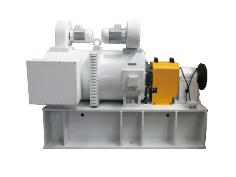
An eddy current dynamometer, used as a load, is a testing device for measuring the various characteristics of power machinery. It is suitable for performance testing of internal combustion engines, medium and small power motors, automotive transmission components, gas turbines, hydraulic turbines, construction machinery, forestry, mining, and petroleum drilling machinery. It can also be used as a power absorption device for other power equipment.
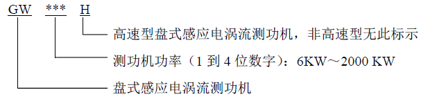
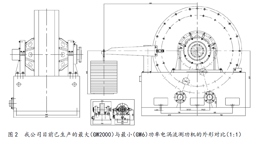
As a high-tech enterprise specializing in power testing instruments for many years, Hunan Xiangyi Power Testing Instrument Co., Ltd. has accumulated rich experience in the design, production, sales, installation, and after-sales service of eddy current dynamometers, and has been recognized by domestic users and exported internationally. Currently, our company's series of disc-type eddy current dynamometers are complete, with a wide testing range, rated test power: 6KW~2000KW, rated torque: 25N.m~14000N.m; rated speed: 3000rpm~12000rpm. The naming method of the dynamometers designed and produced by our company is as follows:
Main Features
Simple structure, easy operation and maintenance;
Large braking torque, high testing accuracy, stable operation;
Small moment of inertia, fast dynamic response speed;
Equipped with a measurement and control system, it can realize automated operation.
Structure and Working Principle
The eddy current dynamometer consists of several parts: a brake, a force measuring mechanism, and a speed measuring device. The brake adjusts the load of the prime mover and simultaneously converts the absorbed power of the prime mover into heat energy, which is then dissipated by water cooling.
The dynamometer measures torque based on the principle that the action torque and reaction torque are equal in magnitude and opposite in direction. Therefore, the measured torque can be indicated by the rotational torque acting on the dynamometer (i.e., the reaction torque of the brake housing).
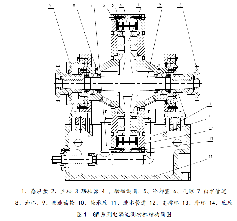
The eddy current dynamometer mainly consists of a rotating part (inductor), a swinging part (armature and excitation part), a force measuring part, and a correction part. The structural diagram of the GW series is shown in Figure 1. As can be seen from the structural diagram, the inductor is shaped like a spur gear, and the eddy current is generated on the side wall of the cooling chamber. When a direct current is applied to the excitation winding, a closed magnetic flux is generated around the excitation winding. When the inductor is driven to rotate by the prime mover, the air gap magnetic density changes periodically with the rotation of the inductor, generating an eddy current potential and eddy current on the surface and within a certain depth of the side wall of the cooling chamber. The magnetic field formed by this eddy current interacts with the air gap magnetic field, generating a braking torque. This torque is transmitted to the force measuring device through the outer ring and the force arm, and the force sensor converts the magnitude of the force into an electrical signal output, thereby achieving the purpose of measuring the torque.
The speed is measured using a contactless magnetic electric speed sensor, which converts the speed signal into an electrical signal.
Main Technical Indicators
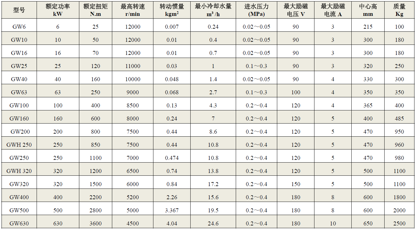
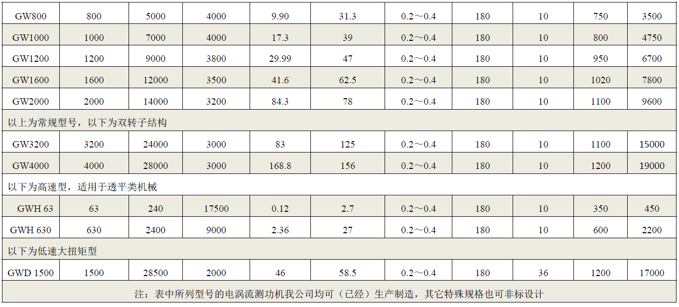
The main technical parameters of the eddy current dynamometer are shown in Table 1, and the others are as follows:
1) Operating ambient temperature: 0℃~45℃
2) Ambient relative humidity not exceeding 85%
3) Cooling medium: Clean fresh water without impurities or debris, see Section 6.5 for details
4) Cooling water pressure: The cooling water inlet pressure should not exceed 0.7MPa, and there should be no back pressure in the cooling water outlet pipe. See Table 1 for details.
5) Dynamometer outlet water temperature: Below 48℃ (The water pressure can be adjusted according to the outlet water temperature. When the outlet water temperature rises, the inlet pressure can be appropriately increased to increase the flow rate and lower the outlet water temperature).
6) Cooling water flow rate: The cooling water flow rate depends on the temperature difference between the inlet and outlet water and the size of the absorbed power. It can be calculated according to the following formula. When the inlet water temperature is 20℃, the water consumption of the dynamometer can be estimated at 40~50L/kW·h.
7) Minimum cooling water flow rate (see Table 1): Considering the maximum allowable outlet water temperature of the dynamometer and the possible highest inlet water temperature in summer, considering the water flow resistance and unevenness inside the dynamometer, regardless of the size of the power absorbed by the dynamometer from the tested prime mover, it must not be less than its minimum inlet flow rate; moreover, the water flow should be stable, and the flow fluctuation should not be >10%, and intermittent interruption is not allowed. When designing the cooling circulating water system, a surplus of no less than 15% should be reserved.
8) Operating direction: Left-hand or right-hand rotation, continuous operation
9) Torque measurement accuracy: ±0.4%FS (Model range GW6~GW100)
Torque measurement accuracy: ±0.2%FS (Model range GW160~GW2000)
10) Speed measurement accuracy: ±1r/min
11) Torque measurement sensor: Strain-type tensile and compressive force sensor
12) Speed measurement sensor: 60 pulse magnetic electric speed sensor
13) Dynamometer characteristic curve, see Figure 4
14) Power calculation of eddy current dynamometer:
The output power of the prime mover is determined by the measured torque and speed.
M——Braking torque on the rotor, N.m;

ω——Angular velocity of the rotor, radians/second;
n——Rotational speed of the rotor, r/min;
P——Output power of the tested prime mover.
Table 1 Main technical parameters of GW series eddy current dynamometers
表1 GW 系列电涡流测功机主要技术参数
Product Inquiry
Sales Hotline:86-731-88317217/88317218/88317220
After-sales Hotline:86-731-88317038
Email:xydc@xydcweb.com
Website:www.xydcweb.con
Address: No. 99, Zhonglu, Maqiaohe Road, Wangcheng Economic Development Zone, Changsha, Hunan,China
Copyright © Hunan Xiangyi Power Testing Instrument Co., Ltd.
This site supports IPv4 IPv6.
Powered by www.300.cn ChangSha