

Hunan Xiangyi Power Testing Instrument Co., Ltd.

SG series water vortex dynamometer
Model: SG400-SG12600
Rated absorption power: 400-12600kW
Speed measurement accuracy: ±1r/min
Torque measurement accuracy: ±0.2%FS
Keywords:
Category:
File Download:
Share to


- Product Description
-
Product Overview
A hydraulic dynamometer, used as a load, is a testing device used to measure the various characteristics of power machinery. It is suitable for performance testing of internal combustion engines, medium and small power motors, automotive transmission components, gas turbines, hydraulic turbines, construction machinery, forestry, mining, and petroleum drilling machinery. It can also be used as a power absorption device for other power equipment.
As a high-tech enterprise specializing in power testing instruments for many years, Hunan Xiangyi Power Testing Instrument Co., Ltd. has accumulated rich experience in the design, production, sales, installation, and after-sales service of hydraulic dynamometers, and has been recognized by domestic users and exported internationally. Currently, our company's hydraulic dynamometer product series is complete, with a wide testing range, rated test power: 400kW~12,600kW, rated torque: 25N.m~180,000N.m; rated speed: 1500rpm~10000rpm.
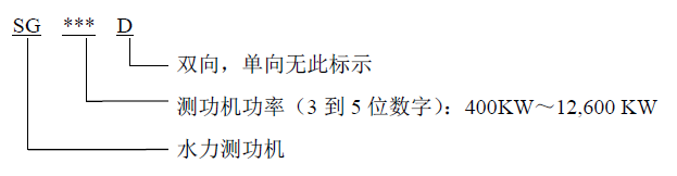
The naming method for the dynamometers designed and produced by our company is as follows:
Main Features
- Medium-speed and high-speed (dual-rotor) designs, more suitable for medium-speed diesel engines;
- Small size (high power absorption capacity per unit mass), easy installation;
- Simple structure, convenient operation and maintenance;
- Large design margin, high braking torque, high allowable speed;
- High-precision tensile pressure sensor with high measurement accuracy and stable and reliable operation;
- Small moment of inertia, fast dynamic response speed;
- Magnetoelectric speed sensor achieves high-precision instantaneous speed measurement;
- Optional electric servo control valve for transient control (full stroke 0.2s);
- Integrated inlet and outlet water temperature, bearing temperature real-time monitoring;
- Equipped with a test and control system, it can realize automated operation.
Hydraulic Dynamometer Product Introduction
Structure of the Hydraulic Dynamometer
Working Principle of the Hydraulic Dynamometer
The rotor of the hydraulic dynamometer is driven by the test motor (engine), and the rotor stirs the cooling water in the working chamber, converting the mechanical energy (speed, torque) of the motor (engine) into thermal energy of the water. The cooling water in the working chamber is both the working medium that absorbs mechanical energy and the cooling medium for heat dissipation. During the test, the magnitude of the braking torque provided by the hydraulic dynamometer is determined by the amount of water stored in the working chamber.
During operation, the hydraulic dynamometer measures the torque and speed on the main shaft.
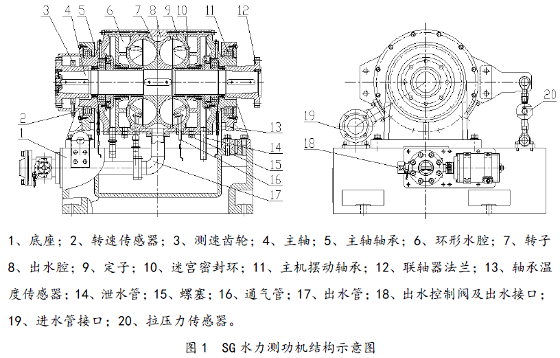
The SG series hydraulic dynamometer mainly includes the following functional components:
1. Dynamometer main unit: Suspended along the axial direction on the main unit swing bearing (part 11), the rotational degree of freedom is limited by the tensile pressure sensor (part 20) fixed to the base (part 1); used to generate braking torque and convert mechanical energy into thermal energy of the cooling water;
2. Outlet water control valve (part 18): Controls the amount of water stored in the working chamber and adjusts the braking torque by adjusting the butterfly valve opening;
3. Inlet water pipe interface (part 19): Connects to the cooling water supply system to continuously supply cooling water to the dynamometer;
4. Dynamometer base (part 1): Is the installation base for the dynamometer main unit and all accessories. A water storage tank is set in the middle of the bottom, which can collect the cooling water discharged from the main unit drain pipe (part 14) and vent pipe (part 16) and discharge it through a pipe.
The test motor, engine (hereinafter collectively referred to as the test power unit) is connected to the rotor main shaft (part 4) through the coupling flange (part 12), thereby transmitting the torque of the test power unit to the dynamometer rotor main shaft (part 4); the dynamometer rotor main shaft is supported by a pair of grease-lubricated bearings (part 5), the bearings are separated from the cooling water in the working chamber by a non-contact sealing device, and the bearings are equipped with a dedicated temperature detection sensor (part 13) for abnormal temperature rise alarm; a rotor (part 7) is installed on the dynamometer main shaft, the rotor has blades, and when the rotor rotates, the blades can accelerate the cooling water, and the accelerated cooling water flows to the stator (part 9), and then is decelerated or changed direction by the stator blades, and the temperature of the cooling water increases during this stirring process. The cooling water is accelerated in the rotor area in the working chamber and decelerated in the stator area.
The magnitude of the braking torque is determined by the amount of water in the working chamber. The cooling water first flows into the inner annular water chamber (part 6) from the inlet pipe, and then flows into the working chamber from the inlet holes on the side wall of the annular water chamber. Under specific operating conditions, the inlet water volume per unit time remains basically constant (mainly determined by the power required to be absorbed by the dynamometer).
The cooling water in the working chamber is connected to the outlet water chamber (part 8) through the gap between the rotor (part 7) and the stator (part 9). Under the action of water pressure, the cooling water flows to the outlet water control valve (part 18). The outlet water control valve controls the opening degree by the water gate controller, thereby controlling the amount of water in the working chamber of the dynamometer and controlling the braking torque of the dynamometer. The outlet valve is connected to the cooling water discharge pipe, and finally discharges the high-temperature cooling water to the cooling water pool.
A speed measuring gear (part 3) is installed at one end of the dynamometer main shaft, and the main shaft speed can be read through the speed sensor (part 2). The dynamometer main unit is supported on the base through the main unit swing bearing (part 11), and the rotational degree of freedom of the dynamometer main unit around the center of rotation is limited by the tensile pressure sensor (part 20) hinged on its outer casing, with only a small angle of rotation (the frictional torque is very small and negligible). In this case, the braking torque on the dynamometer is obtained by multiplying the reading of the tensile pressure sensor by the length of the lever arm.
Special Design
1. Bidirectional Rotating Dynamometer Design
Generally, the rotor and stator blades of the SG series hydraulic dynamometer are designed to be inclined for unidirectional rotation. When the user has a bidirectional rotation requirement for the hydraulic dynamometer, we can design the rotor and stator blades in a straight plate form; in this case, the hydraulic dynamometer can be used for bidirectional rotation, and the maximum absorption power and rated braking torque are consistent with the unidirectional rotation dynamometer, but the characteristic curve is slightly different.
2. Dual-Rotor Dynamometer Design
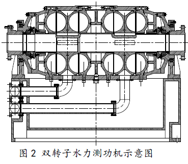
When testing high-speed, high-power engines (e.g., turbo engine testing), two rotors can be designed in series within a dynamometer. In this case, the maximum speed of the dual-rotor dynamometer is the same as that of a single-rotor dynamometer of the same model, but the maximum absorbed power and braking torque can reach twice that of the latter. The schematic diagram of the dual-rotor hydraulic dynamometer is shown below:
Control and Monitoring Unit
1. Braking Monitoring
The SG series hydraulic dynamometer's control system has a braking monitoring unit for monitoring the dynamometer's operation. Under standard configuration, the dynamometer braking monitoring system monitors the dynamometer's operating time, maximum speed, and bearing temperature in real time. When the bearing temperature exceeds the system's maximum allowable value, the braking monitoring system issues a "fault" message and shuts down the test system. This operation avoids subsequent losses (e.g., burning out bearings). During equipment maintenance, the bearing temperature is also monitored in real time by the braking monitoring system during the test run after the bearing is replenished with lubricating grease, and the temperature is displayed in the control system.
2. Cooling Water Monitoring (Optional)
The SG hydraulic dynamometer can be equipped with a cooling water monitoring system to monitor the inlet pressure and outlet temperature of the cooling water. If the pressure or temperature monitoring values exceed the system's allowable safety values during operation, the control system issues a "fault" message and shuts down the test system.
The inlet pressure detection sensor must be installed in the horizontal straight pipe section near the dynamometer inlet. If an inlet control valve is equipped, the pressure sensor should be installed before the inlet control valve. A large height difference between the pressure detection sensor and the dynamometer inlet will invalidate the measurement and lead to unsafe monitoring. The outlet temperature sensor is installed at the outlet of the drain valve.
Installation order of components before the dynamometer inlet (along the water flow direction): pressure controller (optional); water pressure monitoring and signal transmission (optional, close to and installed before the inlet control valve); inlet control valve (optional).
3. Vibration Monitoring (Optional)
The SG hydraulic dynamometer can be equipped with a vibration monitoring system to monitor the vibration of the dynamometer housing in three directions. Generally, six vibration velocity sensors are configured. If the vibration monitoring value exceeds the system's allowable safety value during operation, the control system issues a "fault" message and shuts down the test system.
Main Technical Indicators
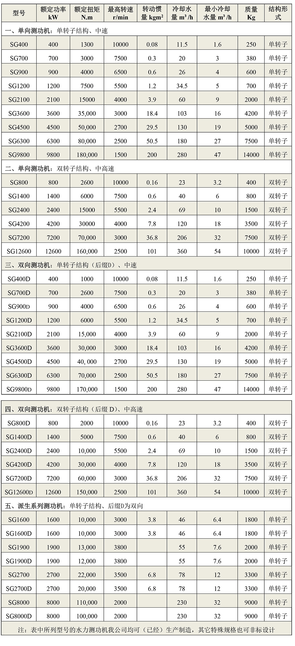
The main technical parameters of the hydraulic dynamometer are shown in Table 1, and the others are as follows:
1) Operating ambient temperature: 0℃~45℃
2) Ambient relative humidity not exceeding 85%
3) Cooling medium: clean fresh water without impurities or debris, see Section 7.1
4) Cooling water pressure: not allowed to exceed 0.06MPa, see Table 5
5) Dynamometer outlet water temperature: below 50℃ (water pressure can be adjusted according to the outlet water temperature. When the outlet water temperature rises, the inlet pressure can be appropriately increased to increase the flow rate and lower the outlet water temperature).
6) Cooling water flow rate: The cooling water flow rate depends on the temperature difference between the inlet and outlet water and the size of the absorbed power. It can be calculated according to the following formula. When the inlet water temperature is 20℃, the water consumption of the dynamometer can be estimated at 40~50L/kW·h.

For specific water consumption, see Figure 3, and it must not be less than the minimum cooling water volume.
7) Minimum cooling water volume (see Table 1): Considering the maximum allowable outlet water temperature of the dynamometer and the possible highest inlet water temperature in summer, considering the water flow resistance and unevenness inside the dynamometer, regardless of the size of the power absorbed by the dynamometer from the tested prime mover, it must not be less than its minimum inlet flow rate; moreover, the water flow should be stable, the flow fluctuation should not be >10%, and intermittent interruption is not allowed. When designing the cooling circulating water system, a surplus of no less than 15% should be reserved.
8) Operating direction: left-hand or right-hand rotation, continuous operation
9) Torque measurement accuracy: ±0.2%FS
10) Speed measurement accuracy: ±1r/min
11) Torque measurement sensor: Strain-type tensile and compressive pressure sensor
12) Speed measurement sensor: 60-pulse magnetic electric speed sensor (120 pulses for some models)
13) Dynamometer characteristic curve, see Figure 3
14) Power calculation of the dynamometer:
The output power of the prime mover is determined by the measured torque and speed.
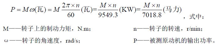
Table 1 Main Technical Parameters of SG Series Hydraulic Dynamometer
Product Inquiry
Sales Hotline:86-731-88317217/88317218/88317220
After-sales Hotline:86-731-88317038
Email:xydc@xydcweb.com
Website:www.xydcweb.con
Address: No. 99, Zhonglu, Maqiaohe Road, Wangcheng Economic Development Zone, Changsha, Hunan,China
Copyright © Hunan Xiangyi Power Testing Instrument Co., Ltd.
This site supports IPv4 IPv6.
Powered by www.300.cn ChangSha